Full-wave rectifier How to calculate ripple frequency of full wave rectifier haiper All about full wave rectifier
Full Wave Rectifier Formula, Efficiency, Circuit, Working
Full-wave bridge rectifier with capacitor filter and ripple voltage Wave full rectifier circuit diagram build Wave rectifier rectifiers conventional
Rectifier equations wave full bridge without filter mvm experts electronics
3 phase rectifier formula shop online todayFull wave rectifier: working principle, diagram, and formula Full wave rectifier: working principle, diagram, and formulaFull wave bridge rectifier.
Full wave rectifier formula, efficiency, circuit, workingFull-wave rectifier dc & rms load current & voltage , efficiency Rectifier circuit diagram without transformerWhat is full wave rectifier, types, woking, rms, operation, piv.
Full wave rectifier circuit working and theory
Full-wave rectifier average value derivationPrecision full wave rectifier circuit diagram Full wave rectifier with capacitorRectifier wave rms voltage current full dc load efficiency.
Rectifier wave circuit full theory capacitor working load rl voltage do bridge diagram calculate half output dc its typesRectifier wave full diode smoothing capacitor bridge circuit Rectifier bridge wave full circuit diagram diode voltage operation fig its shown below inverse peak disadvantages value when negativeRectifier wave average full value derivation circuits derive devices edc electronic.

Full wave diagram
Full wave rectifier circuit diagram ncertRectifier equations wave bridge full filter 2010 experts mvm half august Full-wave rectifierWhat is single phase full wave controlled rectifier? working, circuit.
3 phase rectifier diagramFull-wave rectifier dc output voltage vdc derivation Single phase half wave rectifier- circuit diagram,theory & applicationsMvm-experts: electronics lab experiments-rectifier equations.

Mvm-experts: electronics lab experiments-rectifier equations
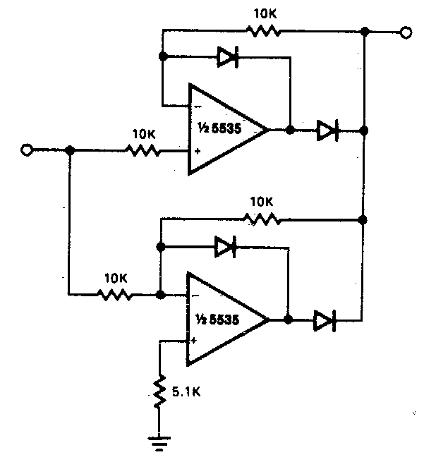
Rectifier circuitWave rectifier circuit full precision sine op amp waveform circuits oscillator rectangular trigger schmitt gr next Mvm-experts: august 2010Rectifier wave circuit precision full diagram simple ac dc circuitsstream sourced circuits gr next.
Precision full wave rectifier circuitFull wave rectifier basics, circuit, working & applications Full wave bridge rectifier – circuit diagram and working principleBuild a full wave rectifier circuit diagram.
How to calculate ripple frequency of full wave rectifier
Rectifier equations wave full bridge filter mvm experts electronics halfFull wave rectifier and bridge rectifier theory Rectifier wave full voltage output dc derivation vdc devices circuits edc electronicFull wave rectifier (form factor & ripple factor).
Phase dc rectifier circuit bridge three single voltage ac power rectified diagram tri vfd 400v convert diodes motor generator bldc .


diodes - if a standard three-phase 400V AC connection is rectified what

full wave diagram - Wiring Diagram and Schematics

Precision full wave Rectifier Circuit Diagram | Super Circuit Diagram

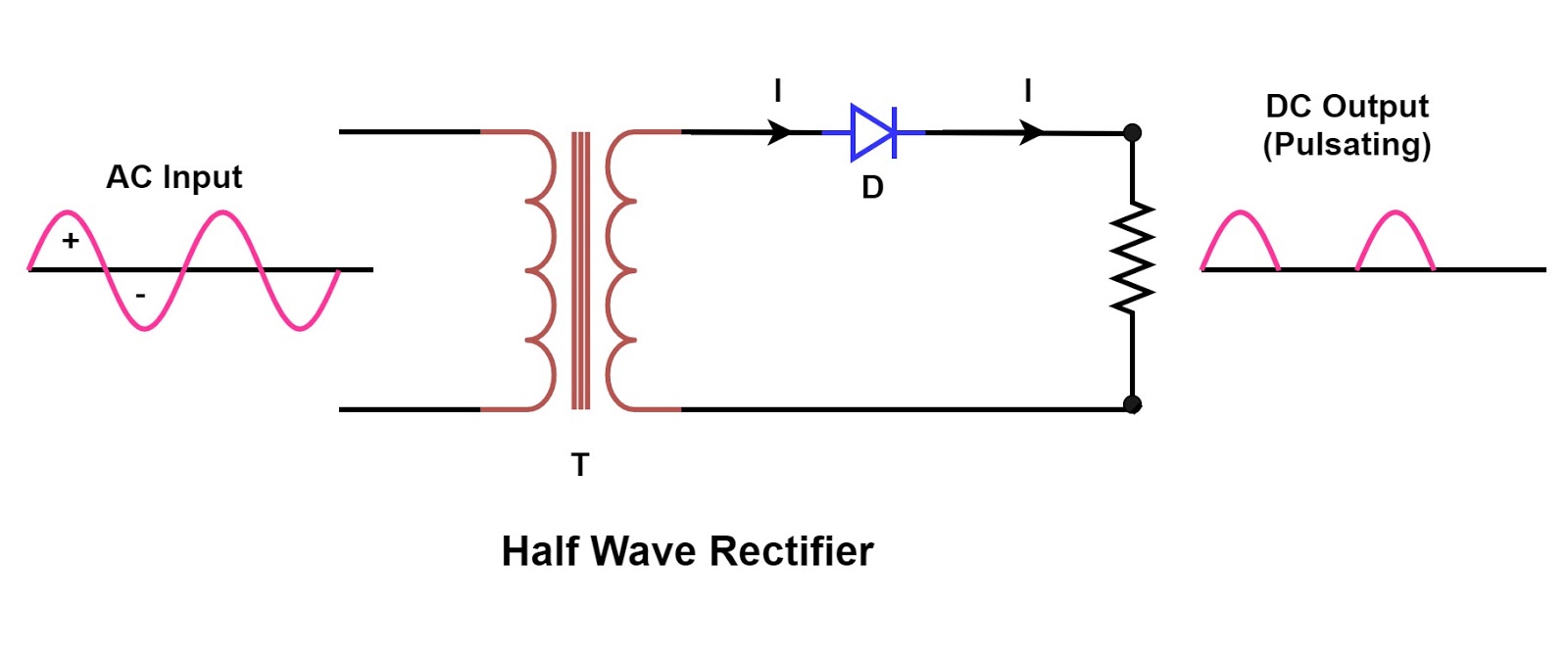
Single Phase Half Wave Rectifier- Circuit Diagram,Theory & Applications

Full Wave Rectifier and Bridge Rectifier Theory

Precision full wave rectifier circuit

Full Wave Rectifier Circuit Diagram Ncert - Circuit Diagram