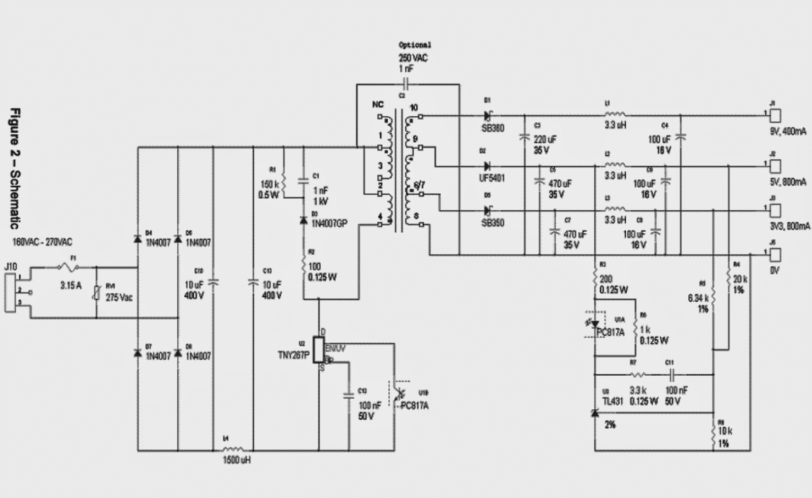
Simple 12v, 1 amp smps with pcb and transformer winding details Self switching power supply project circuit diagram with explanation Smps circuit 12v amp circuits led driver compact diagram ic flyback simple transformer homemade board using schematics understand functions components
How to Modify SMPS for Adjustable Current and Voltage Output - Homemade
52w smps ac-dc adapter 24v 2a smps circuit diagram Electrical – understanding flyback transformer datasheet – valuable
Basic smps circuit diagram
48v smps battery charger circuit diagramComputer smps power supply circuit diagram High current smps circuit diagramSmps philips switching ctv tottenham.
Basic smps circuit diagram소출력 d-클래스 앰프와 굼뜬 smps 어댑터 How to modify smps for adjustable current and voltage outputCircuit smps amp circuits supply 12v power diagram switch simple make transformer mode pcb homemade winding battery led understanding 1a.

24v 2a smps circuit diagram
Schematic diagrams: ctv smps circuit diagram[diagram] battery circuit diagrams 12v 1a smps power supply circuit design on pcbPc smps power supply circuit diagram.
Smps circuit variable voltage projects output driver adjustable transformer optocoupler current ferrite details homemade electronic fixed open ifSmps voltage optocoupler Smps adapter dc ac circuit 52w diagram circuits schematic input universal 16v 2009 simple gr next os µf sanyo conHow to make a variable smps driver circuit ~ electronic circuit projects.

2 compact 12v 2 amp smps circuit for led driver
12v 1 amp smps circuit diagramMaking an adjustable smps circuit Design a 12v 27w smps circuit with uc3843 smps controller ic12v smps circuit diagram.
Atx 12v smps circuit diagram pdfSmps circuit variable voltage output projects adjustable driver current optocoupler transformer homemade ferrite details modify .


12v 1 Amp Smps Circuit Diagram

12V 1A SMPS Power Supply Circuit Design on PCB

How to Modify SMPS for Adjustable Current and Voltage Output - Homemade

Basic Smps Circuit Diagram

Simple 12V, 1 Amp SMPS with PCB and Transformer Winding Details

Self Switching Power Supply Project Circuit Diagram With Explanation

Design a 12V 27W SMPS Circuit with UC3843 SMPS Controller IC

24v 2a Smps Circuit Diagram

48v Smps Battery Charger Circuit Diagram