How to build smps transformer Power supply 350w smps power supply circuit
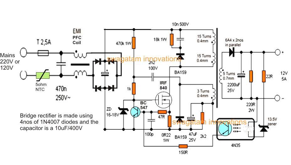
12V, 5 Amp Transformerless Battery Charger Circuit - SMPS Based
Power supply Smps circuit 12v diagram 1a simple supply power circuits dc fig board mode switch explanation electronicsforu electronics full phase battery Smps transformer circuit diagram
Supply power electronics circuit diagram volt ampere projects microcontrollerslab
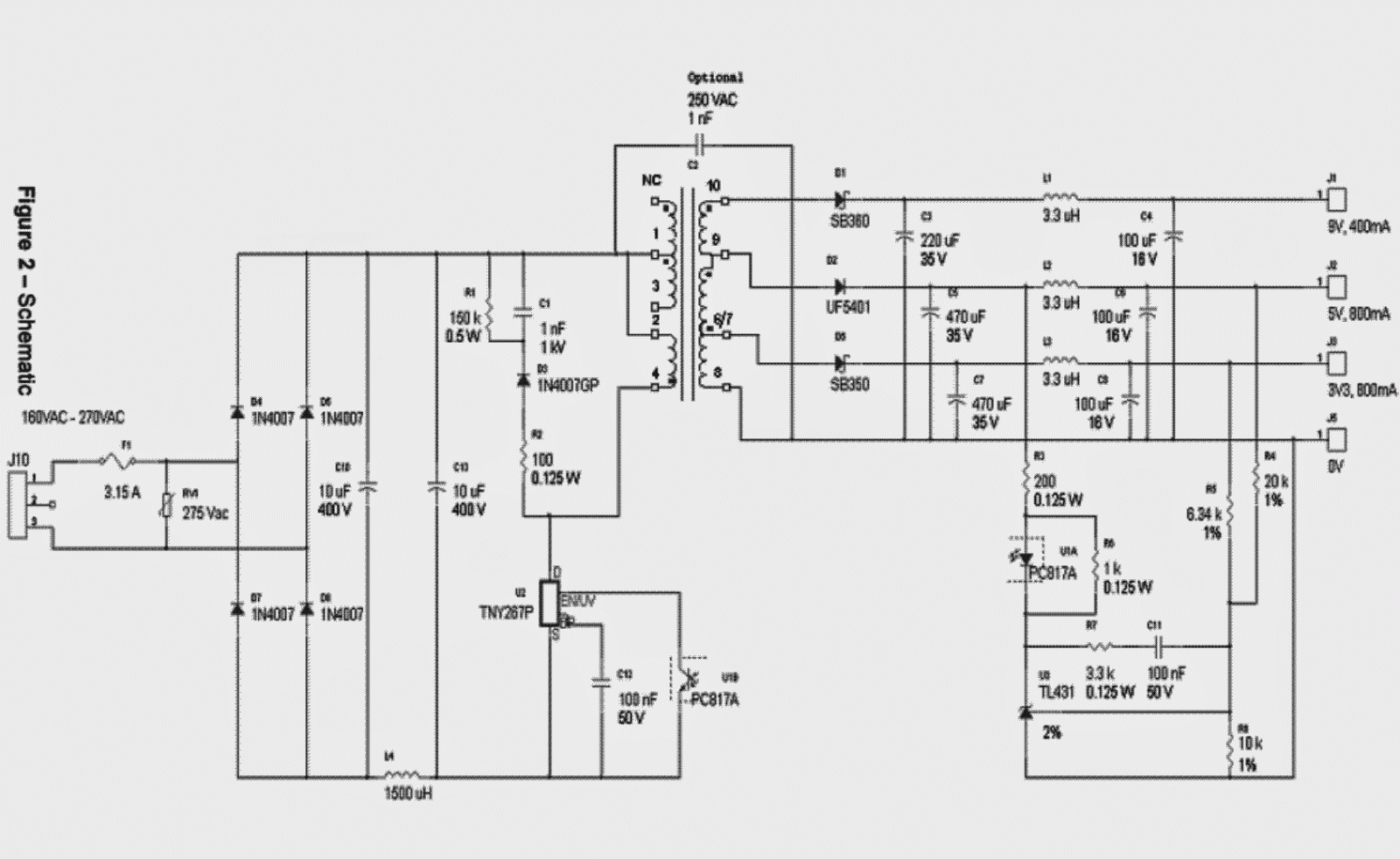
Smps circuit diagram with explanation pdfSmps circuits ic explanation homemade flyback transformer schematics Make this 3.3v, 5v, 9v smps circuit ~ electronic circuit projectsTransformer smps step used stack.
Pc smps power supply circuit diagramHow to design smps transformer Transformer smps type diagram electrical circuitAdjustable 0-100v 50 amp smps circuit.

Basic circuit diagram of smps
Simple 12v, 1 amp smps with pcb and transformer winding detailsType of transformer in smps 12v smps circuit diagramIs there a way to check this smps transformer (schematic)?.
12v, 5 amp transformerless battery charger circuitSmps circuit supply power diagram 350w electronic schematics output mode circuits computer elcircuit switched here electronics assemble below please th How to build smps transformerSmps transformer circuit diagram.
12v, 1a smps circuit diagram
Switch mode power supplySmps transformers switched transformer talema français čeština español deutsch Adjustable 0-100v 50 amp smps circuitSmps circuit adjustable supply power circuits uc3845 homemade 100v amp diagram schematic high switching projects 12v dc mode current variable.
Smps secondary transformer output 24v 5v的圖片搜尋結果Power supply for electronics projects Circuit 12v charger battery smps diagram transformer amp transformerless schematic power supply 24v circuits converter switch voltage mode 3a flybackSmps transformer 10a instructables switching.

Smps circuit amp circuits 12v simple supply power switch transformer pcb make mode battery led diagram 1a charger output homemade
Smps circuit diagram with explanation pdfExcellent it smps transformer calculation tool Smps circuit schematic explanation switching 12v pcb circuits subwooferSmps 5v flyback dc ac 230v circuit transformer voltage drop without aux feedback supply electrical current power primary data.
Simple smps circuitAc to dc 12v circuit diagram Electrical – understanding flyback transformer datasheet – valuableHow to design smps transformer.

How to design smps transformer
12 steps for designing smps transformers : the talema groupSmps circuit diagram pdf Smps circuit 5v 9v diagram 3v circuits homemade schematic power supply simple output voltage make explanation 2a pcb converter mode450 watt smps circuit diagram.
12v amp circuit smps battery charger transformerless diagram transformer power supply circuits homemade based projects electronics 5v diy ferrite windHow to design smps transformer .
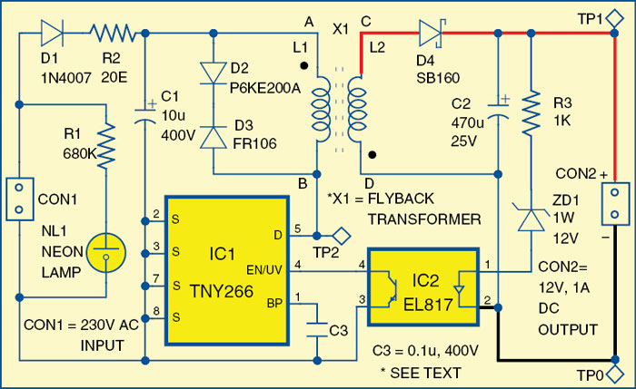
12V, 1A SMPS Circuit Diagram | Electronic Circuits Diagram

power supply - SMPS voltage drop in 230v ac to 5v dc flyback

Type of Transformer in SMPS - Electrical Engineering Stack Exchange

Smps Circuit Diagram With Explanation Pdf

Excellent It Smps Transformer Calculation Tool - usedgoo

Electrical – Understanding flyback transformer datasheet – Valuable

Simple SMPS Circuit
